maandag 7 november 2022

Mosha Eurorack Modules #2: CV Sequencer


The CV Sequencer is a 6 HP module that, as the name implies, sequences control voltages in the range of 0V to 10V in either 15 or 16 steps. The switch has three settings: 15 step playback (top), 16 step playback (middle) or record (bottom). Record mode can also be activated using a CV in the top right jack, so it can modify its own content.

The yellow button can be used to step through, and the jack next to it allows an external clock signal as well. The purple jack is the actual CV that is recorded, but a manual voltage can be supplied with the dial.

Outputs are hexagonal, and the purple output is the actual CV output. The jack next to it is the gate output, which normally should follow the clock. Below are the two indicator LED. The right indicator cycles through 8 different colors for 8 of the 16 steps, the magenta LED on the left has two purposes: it both tracks the other 8 steps, and the fact that the module is in record mode.

The sequencer is built around the PIC16F684 microcontroller with the following pin configuration:

Analog input: voltage to be sampled (RA0, pin 13)
Digital input: clock (RA2, pin 11)
Digital input: write (RA3, pin 4)
PWM output: voltage result (RC5, pin 5)
Gate out (RA1, pin 12)
LED out (RC0, RC1, RC2, RC3, pin 10, 9, 8, 7)
Rhythm select in (RC4, pin 6)
20 MHz crystal: RA5 (pin 2) RA4 (pin 3)

The inputs are merely protected by resistors, there are no protection diodes. The ones inside the PIC16F684 work well enough. The analog input has a jumper that allows halving the voltage using a 1% resistor ladder and buffered to ensure that the impedance is below 10k. 

The PWM output goes through a two-pole RC (100k, 4.7nF) filter network with buffer where the second stage of the buffer is shown in the circuit below. It has a trim pot at the bottom of the module that allows the output to be amplified by 1x to 2.1x. As usual, all OPAMP are the TL074, not the TL081.

The jumper and the trimpot together allow the sequencer to work with a highly accurate 0-5V or a slightly less accurate 0-10V.

The code for the sequencer is available here. The analog imput is sampled multiple times and averaged, to ensure that the lower bits of the value are accurate as well.

zondag 6 november 2022

Mosha Eurorack modules #1: Triple LFO

The triple LFO is a 6 HP module that, as the name implies, as three LFO. 
  • The silver LFO has a -5V to 5V triangle output, a -5V to 5V square wave output and a 0V to 5V square wave output and has a medium speed (~2s to 0.2s).
  • The purple LFO only has a -5V to 5V triangle output and a slow speed (~20s to 2s).
  • The golden LFO has a -5V to 5V triangle output that can be attenuated with the second knob, and a 0V to 5V triangle output. Each of the LFO has an LED indicator that switches between red and green.
The design is based on the Simple LFO design from David Haillant. Modifications include having three different capacitor values, the replacement of the lower bound resistor with a 1.5k instead of a 470 Ohm resistor and having a fixed output path. What wasn't fixed is the missing 1k Ohm resistor at the output, so shorting the LFO can cause it to reset. For the 0V to 5V square wave a diode was added and a pulldown resistor.

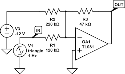
For the 0V to 5V triangle wave the circuit below was added, which basically is an inverting amplifier that adds approximately -5V to the output of the LFO. This causes the LFO to fluctuate between -10V and 0V. The amplifier divides this by 2 and inverts it, resulting in 0V to 5V. Although the circuit mentions the TL081 the entire LFO was built using TL074.


woensdag 4 mei 2022

Building my own Eurorack module

 For my birthday I got a NiftyCase with various modules, and I also bought a Mr Phil Ter and a Monsoon for it. However, it lacked envelopes. I started looking for possible solutions, On my youtube channel you can see a bit more about the synthesizer, here I will describe the design and making of the module. The basic circuit I came up with is as follows:

There's two inputs and an output, one of the inputs is the gate signal, which starts the decay, and the other is the control voltage, which uses and LED to control a photoresistor which is in parallel with a potentiometer, both of which control the length of he decay. The output is multiplied by a certain amount (currently 1.55x, but I may go back to the idea of multiplying by 2x as in the circuit above.

The 85k resistor was changed to 1M, and I added a LED and 470 resistor to show the decay working after the OPAMP (an TL072). This circuit worked, but unfortunately most gate signals are terrible, so I had to add a special PIC10F206 circuit to clean that up. This circuit also discharges the capacitor quickly between uses, avoiding a wait time that was necessary otherwise.

The only improvement still needed is handling of triggers: if the gate signal is too short I want to change the behavior into a release instead of a decay, possibly with a check that the output signal has grown small enough.

Here is what it looks like on the outside, which required some drilling, which was definitely a new experience, and quite scary.

By now I learned that the CEO of the company that makes these specific panels isn't a very nice person, so I may have to reconsider my purchasing strategy here.


zaterdag 19 februari 2022

Syncing the Arturia MicroBrute with the Pocket Operator 32

 Today I wanted to do the reverse of the previous project: having the Arturia MicroBrute control the Pocket Operator 32. This is relatively easy (one video states it takes only 17 seconds) by just hooking up the MicroBrute's Gate Out to the Pocket Operator Sync In, but as I previously mentioned the issue here is that the output is 10V peak-to-peak and the input is 5V peak-to-peak maximum. It still works, which is great, but there have been reports of Pocket Operators freezing at certain battery levels and in general it isn't a good idea to run something out of specification.

Fortunately the circuit I made has a very lenient input, and can also be used to convert the 10V of the MicroBrute into the 5V necessary for the Pocket Operator. I plugged everything in, switched the PO-32 to sync mode 2, and everything worked fine.

You can see it working in the following video:


vrijdag 11 februari 2022

Soldered version of the PO-32 to Arturia MicroBrute sync

 As I still had a few prototype PCB boards I decided to make a soldered version of the syncer I previously designed. I added a power plug to it, so I can splice the power off the MicroBrute into this circuit. The power circuit is the usual LM7805 implementation seen elsewhere on this blog. As you can see from the pictures, my soldering skills haven't improved, but they suit the purpose, which is to make a nearly unbreakable version of the board.


I like my trick of putting the connectors at the edge of the board like this, so I don't need to drill larger holes for the pins. I chose pink for the connector to the PO-32 because Teenage Engineering sounds more playful, and because that plug is red, so I know what to match it to. Next will be to set this up and start making a song with it.

There was one soldering mistake that I had to fix, a blob of solder had fallen between two of the lines. This caused the circuit to just play a single note initially. But with my multimeter it was easy to figure out.

woensdag 9 februari 2022

Video for the PO-32 to MicroBrute sync project

I made a short video showing how the sync circuit of the previous post works:


I've not made many of such videos yet, and I clearly need some work on figuring out how to set this up better, but hopefully it shows the most important aspects.

The details are as follows:

  • 3.5mm stereo male to two 3.5mm mono male splitter cable, one goes to the circuit as shown, the other to a MouKey MAMX3 mixer.
  • The PO-32 is in SY1 mode, which can be done using the * button combined with the BPM button.
  • The Arturia MicroBrute is in "gate" mode, this can be configured with the program on a PC hooked up through the USB port.
  • The Arturia MicroBrute has a recorded sequencer pattern, ideally with a length matching the drum pattern (16 beats, usually).
  • The first note of the pattern will be the note played on the keyboard.

In the schematic the 100k Ohm resister IS the Arturia MicroBrute. There is no need to actually put the resistor in the circuit. I added it to aid the simulation.

maandag 7 februari 2022

Pocket Operator (PO-32) to Arturia Microbrute sync

Two birthdays ago I received an Arturia Microbrute which I did very little with so far. Instead I worked on a system combining a Yamaha CS, the Pocket Operator PO-32 by teenage engineering and a TASCAM digital recorder/mixer. However, lately I've become interested in Eurorack modular synthesizers and I discovered that the Arturia Microbrute has some (quite limited) patch options. I also became curious whether it would be possible to include the PO-32 into the modular system and discovered that it has a sync signal, both going in and out and I was curious if I could use this to have the PO-32 control the Arturia Microbrute.

The Internet has quite a few resources here, most of which have the Arturia Microbrute's Gate Out connected to the sync in from the pocket operator (e.g. https://www.youtube.com/watch?v=WIobsEA-_cA). Although this seems to work, if you research it closer there are some warnings here. The Arturia Microbrute's Gate Out is rated 10V peak-to-peak, whereas the pocket operator manual states that the sync signal should not exceed 5V peak-to-peak. From all the youtube videos on this it seems it usually works, and definitely doesn't destroy the pocket operator, but there are reports of the pocket operator freezing at certain battery levels. I suspect this all can be easily voided with a resistor network, and I'll work on that soon. However, I was more curious whether it was possible to have the Microbrute get the sync signal from the Pocket Operator through the Gate In.

Unfortunately the Gate In of the Microbrute expects a 5V peak-to-peak minimum (I suspect it can handle up to 12V) and the Pocket Operator seems to output not more than 1V, as shown on p0k3t0's blog. As you know, I faced a problem like this in the past with the RS-232 conversion for the PIC microcontroller, and I thought that I could use the same circuit here. Unfortunately the RS-232 conversion also required an invert, which is not useful here, so I decided to link two together to form the following circuit:

I'm sure a smaller version is possible, but as shown it is very lenient, it's very accepting to different voltages, and the output's voltage is basically whatever voltage you run the circuit at. 4.5V seems to be enough for the Arturia Microbrute, though.


Here is a picture of the working prototype I made. I can make a video later.

I used circuitlab to make this circuit diagram, also because it allows you to simulate the result:

It shows that a 0V input voltage results in a 0V output, and a 1V input results in a 4.5V output. When you change the voltage of the circuit to 12V it will adjust accordingly.

The simulator also allows me to measure current usage, which is 2.3mA, which seems acceptable.