maandag 30 maart 2009

Pattern


I succeeded in creating a two part pattern loop. An issue was that blanking the image in between each shift caused the LED to be less bright. By adding a delay the impact of the blank could be reduced, however, initially there was too much delay and the pattern seemed to be blinking. The correct code is as follows:


PatternDelay
call Blank
movf p1,w
movwf PORTC
movf p1+1,w
movwf PORTB
call SmallDelay
call Blank
movf p2,w
movwf PORTC
movf p2+1,w
movwf PORTB
call SmallDelay
decfsz delay+1,f
goto PatternDelay
decfsz howlong,f
goto PatternDelay
retlw 0


Here the two patterns are in p1 and p2. As you can see it is relatively easy to extend to more patterns. The next step would be to write an application that can find the minimum sets needed to display a certain pattern.
zondag 29 maart 2009

Figures

Today I tried to create the first figure on the LED cube, an O. In order to do this I had to switch between two patterns, two dots at the bottom in the middle and at the top in the middle, and two dots to the left in the middle and at the right in the middle. The trick was ensuring that the screen is blank in between, because any transistion LED will seem lit as well. The code became:


Display
call Blank
movlw 96
movwf PORTC
movlw 6+96
movwf PORTB
call Blank
movlw 144
movwf PORTC
movlw 9+144
movwf PORTB
goto Display
Blank
movlw 240
movwf PORTC
clrf PORTB
retlw 0


Next step would be to have the delay loop automatically switch between two patterns... Although I might need more than two for complex figures. At 20 MHz it is completely invisible that such switching is taking place, except for the LED being slightly dimmer. Biggest problem is still that the bottom LED make it seem like the LED at the top are slightly lit. I might need to reduce their transparancy somehow.

zaterdag 28 maart 2009

Second layer of LED cube


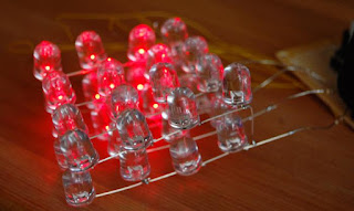
After the set back I finished the second layer of the LED cube, which you can see in action here. A small problem is that the second layer of LED actually responds to the light of the lower layer. It creates a strange effect, but maybe won't work really well... We'll have to see once it's finished.

maandag 23 maart 2009

LED cube problem

I woke up in the middle of the night (which usually doesn't happen) with the thought that my idea of reversing the polarity of the LED in the matrix to double the number of LED I can control wouldn't work. I drew a small version on a piece of paper, and indeed: it doesn't work. There is no combination of control signals that will allow me to turn on only one LED. It's fortunate that I discovered this now, instead of after soldering the next layer of LED. I can still control the cube with 16 lines, but I'll have to use a matrix of 8x8 divided in 4 4x4 segments rather than using two 4x4x2 segments. There will be a switching issue, but at 20 MHz this shouldn't create a big problem.

zondag 22 maart 2009


Here is the first attempt at getting the cube to work. One line of one layer only, but the rest should follow quickly: the other lines are only three wires away, and the second layer is a matter of just adding the LED. Then I will have to repeat it for the next layer.

Processor board

After I cycled against and with the wind to Radioshack (the closest, but not the cheapest supplier of PCB in my area) I was able to start soldering together the board shown. It is the typical board I make, with a 6 pin ICSP for connecting the Pickit 2, a 8-12V power supply input using a 2.1mm jack (standard) and a 20 MHz resonator (not very accurate, but accuracy seems not very important in a LED cube. The speed is useful for making special effects, which I'll probably never write). As said I'm using the 16F57, mostly because I had one around and it has two full ports (PORTB and PORTC) that can be used to control the cube. PORTB will have to share bits with the ICSP, but that shouldn't be a problem. After soldering the board I tested it, and it didn't immediately work, but that was because I didn't realise the PIC16F57 is actually not a 16-series PIC, but a base model PIC. After switching the programming software to recognize base PIC, it all worked fine. My voltage meter is running out of power, so it was giving the clearly wrong voltage of 6.3V from USB and the 7805. I'll have to buy a new battery for it.

zaterdag 21 maart 2009

LED part 2

I know, progress is rather slow, but here is the next part, and basically the ground floor of the LED cube. I also added the required resistors. I didn't have a PCB so I couldn't hook it up yet, but I did decide on the PICmicro to use: the rather obscure PIC16F57 which happened to be in one of the boxes that I got for winning the Microchip Innovation competition. I need to check on it, but it has 28 pins so I'm pretty sure I can use two full PORT for outputting the data, which would reduce the requirement for quick switching between patterns. I already tried lighting one of the LED, and they burn rather brightly, and are visible from the side as well. I'm still not sure if the next layer should face up as well, but it is probably best if they do.

donderdag 12 maart 2009

LED part 1

The LED arrived, and they were nicer than I thought: they actually look transparent, which is much more useful for the cube idea. I started soldering them together, here are the first 8. I'll probably need to devise some plastic covering to ensure that the wires don't cross once I start bending the whole thing into a proper shape.